2. 四川大学 制造科学与工程学院,四川 成都 610065;
3. 遵义师范学院 工学院,贵州 遵义 563000
2. School of Manufacturing Sci. and Eng., Sichuan Univ.,Chengdu 610065,China;
3. School of Eng. and Technol.,Zunyi Normal College, Zunyi 563000,China
齿廓与齿线是齿轮的2个主要特征,也是影响齿轮齿面形状、啮合特性和接触特性的主要因素。变双曲圆弧齿线圆柱齿轮作为一种新型圆柱齿轮,其齿向线形状为圆弧曲线,轮齿的中间截面齿廓线为渐开线,其平行于中截面的各端面齿廓线为均匀变化的双曲线的包络线,故其命名为变双曲圆弧齿线圆柱齿轮。
变双曲圆弧齿线圆柱齿轮具有啮合性能好、重合度大、承载力强、传动效率高、安装精度要求低、无轴向分力等特点[1–3]。该新型齿轮由曲线锥齿轮衍生而来,发展成为圆弧齿线圆柱齿轮,直到现在的变双曲圆弧齿线圆柱齿轮[4–5]。长谷川吉三郎等[6]于上世纪首次将圆弧齿线应用到圆柱齿轮上,从而发明了圆弧齿线圆柱齿轮,并用切齿的方法研制了加工该齿轮的切齿机床。Koga[7]采用了切削刀具与齿坯成一定的倾角的方法,通过刀具做旋转运动而得到圆弧齿线齿廓,这种方法得到的轮齿凹凸齿面能实现共轭啮合。但他们所提出的制造方法所加工的齿轮表面粗糙,啮合不理想,加工出的变双曲圆弧齿线圆柱齿轮不同轮齿的凹凸齿面曲率差异甚大,导致实际接触区域变小,承载能力下降。祝海林等[8]对圆弧齿线圆柱齿轮的啮合理论进行了一定程度的研究,并得到了轮齿齿面根切的界限模型。郑江[9]、邹旻[10]、戴玉堂等[11]对圆弧齿线圆柱齿轮的啮合理论、根切及加工方法进行进一步的探讨与研究。Tseng等[12–14]对圆弧齿线圆柱齿轮的接触特性及轮齿齿面数学模型进行了相关分析研究,并取得了一些相关研究成果。狄玉涛等[15–16]讨论了啮合干涉、轴线平行误差、中心距变化对圆弧齿线圆柱齿轮啮合性能的影响,并提出了齿面应力和弯曲应力计算方法和变位概念,但是没有对齿面的曲率变化特性进行研究。宋爱平等[17–18]采用铣削的方法加工渐开线曲线圆柱齿轮,其齿形等同于渐开线齿形沿圆弧拉伸,该方法可以建立理想的渐开线圆弧齿线圆柱齿轮,但成型原理不符合加工原理,并且齿面沿齿廓方向的曲率变化与渐开线齿面的曲率变化毫无差异。侯力等[19–22]最初在分析变双曲圆弧齿线圆柱齿轮加工原理和数学建模的基础上先后利用MAPLE、UG GRIP语言实现了齿轮理论模型的参数化造型,实现面向制造的3维造型和快速原型制造,但该方法所建立的3维模型不太精确,其模型质量不高,存在一定的误差。赵斐等[23]系统地对变双曲圆弧齿线圆柱齿轮的齿面方程进行了推导,但是并未在精准的齿面基础上对齿面曲率特性进行研究。综上所述,目前国内外学者对变双曲圆弧齿线圆柱齿轮的成型原理和强度理论进行了深入的研究,但对该齿轮的法曲率、主曲率、平均曲率、高斯曲率和诱导法曲率的研究较少,尤其利用微分几何和空间啮合理论对该齿轮的曲率进行系统的推导几乎没有。而主曲率和法曲率是反映齿面的几何特性和某点的弯曲程度的基本参数;高斯曲率和平均曲率是反映齿面特征的基本参数,通过高斯曲率和平均曲率可直观地看出齿面的凹凸变化情况等;齿轮副共轭齿面之间的曲率关系决定着齿轮传动质量的好坏,对齿面诱导法曲率、接触区的形状、接触特性、磨损、润滑条件和齿面压应力都有直接的影响。尤其诱导法曲率是决定变双曲圆弧齿线圆柱齿轮副的接触强度和润滑条件好坏的重要因素,因此对变双曲圆弧齿线圆柱齿轮的曲率特性研究是很有必要的。
作者利用微分几何和齿轮啮合原理对变双曲圆弧齿线圆柱齿轮的曲率特性进行系统的研究,得到齿面曲率的变化趋势,可为齿轮的工业化应用提供一定的理论基础。
1 变双曲圆弧齿线圆柱齿轮齿面方程变双曲圆弧齿线圆柱齿轮的加工方法与准双曲锥齿轮的加工方法类似,主要由安装在旋转主轴上的刀盘和齿轮毛坯之间的相互运动完成,即在轮齿成型的过程中,刀具的内外刀刃与刀具轴线之间始终存在固定角度,即刀具压力角
作者利用以上加工原理,建立如图1所示的空间坐标系。其中,
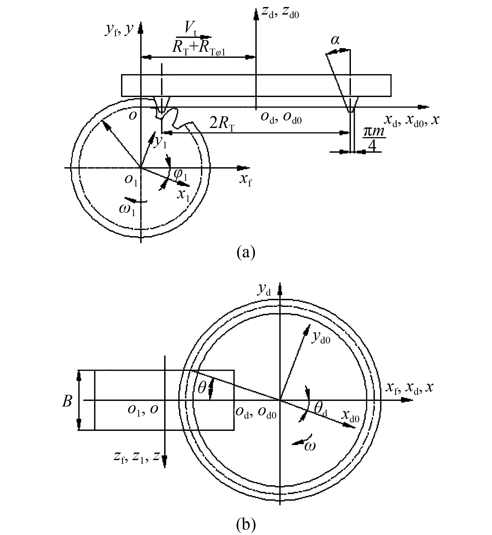 |
| 图1 大刀盘双刃铣削加工原理坐标系 Fig. 1 Machining principle coordinate system with great cutter head |
根据图1可得到刀具曲面在动坐标系
| $\left\{ \begin{aligned}& {x_{\rm d}} = - ( \pm u\sin \; \alpha + {R_{\rm T}} \pm \displaystyle\frac{{\text{π} m}}{4})\cos \;\theta ,\\& {y_{\rm d}} = ( \pm u\sin\; \alpha + {R_{\rm T}} \pm \displaystyle\frac{{\text{π} m}}{4})\sin \;\theta ,\\& {{\textit{z}}_{\rm d}} = u\cos\; \alpha \end{aligned} \right.$ | (1) |
式中:u为刀具曲面上任意点沿刀刃到参考点位移;
从坐标系
| ${{A}_{\rm od}} = \left[ {\begin{array}{*{20}{c}}1 & 0 & 0 & {{R_1}{\varphi _1} + {R_{\rm T}}}\\0 & 0 & 1 & 0\\0 & { - 1} & 0 & 0\\0 & 0 & 0 & 1\end{array}} \right]$ | (2) |
式中,R1为被加工齿轮的分度圆半径,φ为齿轮转角。
从坐标系
| ${{A}_{\rm fo}} = \left[ {\begin{array}{*{20}{c}}1 & 0 & 0 & 0\\0 & 1 & 0 & {{R_1}}\\0 & 0 & 1 & 0\\0 & 0 & 0 & 1\end{array}} \right]$ | (3) |
从坐标系
| ${A_{\rm 1f}} = \left[ {\begin{array}{*{20}{c}}{\cos \;{\varphi _1}} & { - \sin\; {\varphi _1}} & 0 & 0\\{\sin\; {\varphi _1}} & {\cos \;{\varphi _1}} & 0 & 0\\0 & 0 & 1 & 0\\0 & 0 & 0 & 1\end{array}} \right]$ | (4) |
则得到从坐标系
| ${{A}_{\rm 1d}} = {{A}_{\rm 1f}}{{A}_{\rm fo}}{{A}_{\rm od}}$ | (5) |
根据空间啮合原理和微分几何[24–25],利用刀具与齿坯之间的相互运动关系,基于刀具曲面参数方程和相应的坐标变换矩阵,得到了变双曲圆弧齿线圆柱齿轮的齿面方程如式(6)所示:
| $\left\{ \begin{aligned}& x = [ - ( \pm u\sin \; \alpha + {R_{\rm T}} \pm \displaystyle\frac{{\text{π} m}}{4})\cos \; \theta + {R_{\rm T}} + R\varphi ]\cos \; \varphi - (R + u\cos \; \alpha )\sin \; \varphi, \\[5pt]& y = [ - ( \pm u\sin \alpha + {R_{\rm T}} \pm \displaystyle\frac{{\text{π} m}}{4})\cos \; \theta + {R_{\rm T}} + R\varphi ]\sin \; \varphi + (R + u\cos \; \alpha )\cos \; \varphi, \\[5pt]& {\textit{z}} = - ( \pm u\sin \; \alpha + {R_{\rm T}} \pm \displaystyle\frac{{\text{π} m}}{4})\sin \; \theta, \\[5pt]& u = \mp \displaystyle\frac{{\sin \; \alpha }}{{\cos \; \theta }}[\cos \; \theta ({R_{\rm T}} \pm \displaystyle\frac{{\text{π} m}}{4}) - ({R_{\rm T}} + R\varphi )]\end{aligned} \right.$ | (6) |
式(6)为大刀盘铣削加工一个齿槽所得凹、凸齿面的齿面方程。式中:“±”取正号时表示凹齿面,取负号时表示凸齿面;该齿面是由刀具参数
变双曲圆弧齿线圆柱齿轮副中的齿面动点P在空间内随着齿面参数
| $\begin{align}{{\mathit{\boldsymbol{r}}}_1}(\theta ,\varphi ) & = {x_1}(\theta ,\varphi ){\mathit{\boldsymbol{i}}} + {y_1}(\theta ,\varphi ){\mathit{\boldsymbol{j}}} + {\textit{z}_1}(\theta ,\varphi ){\mathit{\boldsymbol{k}}}=\\[4pt]& \left\{ {[ - (u\sin \;\alpha + {R_{\rm T}} + \frac{{\text{π} m}}{4})\cos \;\theta + {R_{\rm T}} + {R_1}{\varphi _1}]\cos \;{\varphi _1} - ({R_1} + u\cos \;\alpha )\sin \;{\varphi _1}} \right\}{\mathit{\boldsymbol{i}}}+\\[4pt]& \left\{ {[ - (u\sin \;\alpha + {R_{\rm T}} + \frac{{\text{π} m}}{4})\cos \;\theta + {R_{\rm T}} + {R_1}{\varphi _1}]\sin \;{\varphi _1} + ({R_1} + u\cos \;\alpha )\cos \;{\varphi _1}} \right\}{\mathit{\boldsymbol{j}}}+\\[4pt]& \left\{ { - (u\sin \;\alpha + {R_{\rm T}} + \frac{{\text{π} m}}{4})\sin \;\theta } \right\}{\mathit{\boldsymbol{k}}}\end{align}$ | (7) |
| $\begin{align}{{\mathit{\boldsymbol{r}}}_2}(\theta ,\varphi ) & = {x_2}(\theta ,\varphi ){\mathit{\boldsymbol{i}}} + {y_2}(\theta ,\varphi ){\mathit{\boldsymbol{j}}} + {\textit{z}_2}(\theta ,\varphi ){\mathit{\boldsymbol{k}}}=\\[4pt] & \left\{ {[ - (u\sin \;\alpha + {R_{\rm T}} + \frac{{\text{π} m}}{4})\cos \;\theta + {R_{\rm T}} + {R_2}{\varphi _2}]\cos \;{\varphi _2} - ({R_2} - u\cos \alpha )\sin \;{\varphi _2}} \right\}{\mathit{\boldsymbol{i}}}+\\[4pt] & \left\{ { - [ - (u\sin \;\alpha + {R_{\rm T}} + \frac{{\text{π} m}}{4})\cos \;\theta + {R_{\rm T}} + {R_2}{\varphi _2}]\sin \;{\varphi _2} - ({R_2} - u\cos \;\alpha )\cos \;{\varphi _2}} \right\}{\mathit{\boldsymbol{j}}}+\\[4pt] & \left\{ { - (u\sin \;\alpha + {R_{\rm T}} + \frac{{\text{π} m}}{4})\sin \;\theta } \right\}{\mathit{\boldsymbol{k}}}\end{align}$ | (8) |
| ${{\mathit{\boldsymbol{r}}}_{1\theta }} \!=\! \frac{{\partial {x_1}}}{{\partial \theta }}{\mathit{\boldsymbol{i}}} \!+\! \frac{{\partial {y_1}}}{{\partial \theta }}{\mathit{\boldsymbol{j}}} \!+\! \frac{{\partial {\textit{z}_1}}}{{\partial \theta }}{\mathit{\boldsymbol{k}}};\;\;{{\mathit{\boldsymbol{r}}}_{1\varphi }} \!=\! \frac{{\partial {x_1}}}{{\partial {\varphi _1}}}{\mathit{\boldsymbol{i}}} \!+\! \frac{{\partial {y_1}}}{{\partial {\varphi _1}}}{\mathit{\boldsymbol{j}}} \!+\! \frac{{\partial {\textit{z}_1}}}{{\partial {\varphi _1}}}{\mathit{\boldsymbol{k}}}$ | (9) |
其中,
| $\begin{align}& {\frac{{\partial {x_1}}}{{\partial \theta }} = (u\sin \; \alpha + {R_{\rm T}} + \frac{{\text{π} m}}{4})\cos \;{\varphi _1}\sin \;\theta + (\sin \; \alpha \sin \;{\varphi _1}\cos \;\theta + \cos \;\alpha \sin \;{\varphi _1})\frac{{\sin \;\theta \sin \; \alpha }}{{{{\cos }^2}\theta }}({R_{\rm T}} + {R_1}{\varphi _1}),}\\[4pt]& {\frac{{\partial {y_1}}}{{\partial \theta }} = (u\sin \; \alpha + {R_{\rm T}} + \frac{{\text{π} m}}{4})\sin \;{\varphi _1}\sin \;\theta + (\sin \; \alpha \sin \;{\varphi _1}\cos \;\theta - \cos \;\alpha \cos \;{\varphi _1})\frac{{\sin \;\theta \sin \; \alpha }}{{{{\cos }^2}\theta }}({R_{\rm T}} + {R_1}{\varphi _1}),}\\[4pt]& {\frac{{\partial {{\text{z}}_1}}}{{\partial \theta }} = - (u\sin \; \alpha + {R_{\rm T}} + \frac{{\text{π} m}}{4})\cos \;\theta + \frac{{{{\sin }^2}\theta {{\sin }^2}\alpha }}{{{{\cos }^2}\theta }}({R_{\rm T}} + {R_1}{\varphi _1}),}\\[4pt]& {\frac{{\partial {x_1}}}{{\partial {\varphi _1}}} = [(u\sin \; \alpha + {R_{\rm T}} + \frac{{\text{π} m}}{4})\cos \;\theta - ({R_{\rm T}} + {R_1}{\varphi _1}) - {R_1}\frac{{\sin \; \alpha \cos \;\alpha }}{{\cos \;\theta }}]\sin \;{\varphi _1} - ({R_1}{{\sin }^2}\alpha + u\cos \;\alpha )\cos \;{\varphi _1},}\\[4pt]& {\frac{{\partial {y_1}}}{{\partial {\varphi _1}}} = [ - (u\sin \; \alpha + {R_{\rm T}} + \frac{{\text{π} m}}{4})\cos \;\theta + ({R_{\rm T}} + {R_1}{\varphi _1}) + {R_1}\frac{{\sin \; \alpha \cos \;\alpha }}{{\cos \;\theta }}]\cos \;{\varphi _1} - ({R_1}{{\sin }^2}\alpha + u\cos \;\alpha )\sin \;{\varphi _1},}\\[4pt]& {\frac{{\partial {{\text{z}}_1}}}{{\partial {\varphi _1}}} = {R_1}{{\sin }^2}\alpha \frac{{\sin \;\theta }}{{\cos \;\theta }}\text{。}}\end{align}$ |
同理,可求得齿轮2齿面的切向量分别为:
| ${{\mathit{\boldsymbol{r}}}_{2\theta }} \!=\! \frac{{\partial {x_2}}}{{\partial \theta }}{\mathit{\boldsymbol{i}}} \!+\! \frac{{\partial {y_2}}}{{\partial \theta }}{\mathit{\boldsymbol{j}}} \!+\! \frac{{\partial {\textit{z}_2}}}{{\partial \theta }}{\mathit{\boldsymbol{k}}},\;\;{{\mathit{\boldsymbol{r}}}_{2\varphi }} \!=\! \frac{{\partial {x_2}}}{{\partial {\varphi _2}}}{\mathit{\boldsymbol{i}}} \!+\! \frac{{\partial {y_2}}}{{\partial {\varphi _2}}}{\mathit{\boldsymbol{j}}} \!+\! \frac{{\partial {\textit{z}_2}}}{{\partial {\varphi _2}}}{\mathit{\boldsymbol{k}}}\!\!\!\!$ | (10) |
齿轮2齿面的切向量分量与齿轮1的形式相同,由于篇幅有限,这里就不再赘述。
变双曲圆弧齿线圆柱齿轮副的齿面单位法向量可根据式(11)求得:
| ${\mathit{\boldsymbol{n}}} = \frac{{{{\mathit{\boldsymbol{r}}}_\theta } \times {{\mathit{\boldsymbol{r}}}_\varphi }}}{{\left| {{{\mathit{\boldsymbol{r}}}_\theta } \times {{\mathit{\boldsymbol{r}}}_\varphi }} \right|}}$ | (11) |
变双曲圆弧齿线圆柱齿轮的法曲率可表示为:
| $\begin{align}{K_{\rm N}}= & \frac{{L{\rm d}{\theta ^2} + 2M{\rm d}\theta {\rm d}\varphi + N{\rm d}{\varphi ^2}}}{{E{\rm d}{\theta ^2} + 2F{\rm d}\theta {\rm d}\varphi + G{\rm d}{\varphi ^2}}}= \\[4pt]& \frac{{{{\mathit{\boldsymbol{r}}}_{\theta \theta }} \cdot {\mathit{\boldsymbol{n}}}{\rm d}{\theta ^2} + 2{{\mathit{\boldsymbol{r}}}_{\theta \varphi }} \cdot {\mathit{\boldsymbol{n}}}{\rm d}\theta d\varphi + {{\mathit{\boldsymbol{r}}}_{\varphi \varphi }} \cdot {\mathit{\boldsymbol{n}}}{\rm d}{\varphi ^2}}}{{{{({{\mathit{\boldsymbol{r}}}_\theta })}^2}{\rm d}{\theta ^2} + 2{{\mathit{\boldsymbol{r}}}_\theta } \cdot {{\mathit{\boldsymbol{r}}}_\varphi }{\rm d}\theta {\rm d}\varphi + {{({{\mathit{\boldsymbol{r}}}_\varphi })}^2}{\rm d}{\varphi ^2}}}\end{align}$ | (12) |
主曲率可以反映齿面的几何特性,齿轮在啮合过程中任意啮合点存在的2个正交的主方向都具有不同的主曲率值。根据文献[24–25]可知主曲率K1和K2是由齿面高斯曲率K和平均曲率H构成的一元二次方程的根,其中齿轮的主曲率可表示为:
| ${K_1}{\rm{ = }}H + \sqrt {{H^2} - K} $ | (13) |
| ${K_2}{\rm{ = }}H - \sqrt {{H^2} - K} $ | (14) |
变双曲圆弧齿线圆柱齿轮齿面高斯曲率K和平均曲率H反映了齿面的几何特征,它们是反映齿面光滑质量和齿面数据点连接质量的主要参考指标,齿轮的高斯曲率决定了齿面的内在性质,反映了齿面的凹凸特性,其表达式为:
| $K = \frac{{LN - {M^2}}}{{EG - {F^2}}} = \frac{{{{\mathit{\boldsymbol{r}}}_{\theta \theta }} \cdot {{\mathit{\boldsymbol{r}}}_{\varphi \varphi }} \cdot {{\mathit{\boldsymbol{n}}}^2} - {{\left( {{{\mathit{\boldsymbol{r}}}_{\theta \varphi }} \cdot {\mathit{\boldsymbol{n}}}} \right)}^2}}}{{{{{\mathit{\boldsymbol{r}}}}_{\theta}^2} \cdot}{{{{\mathit{\boldsymbol{r}}}}_{\varphi } ^2}\cdot}-{{\left( {\mathit{\boldsymbol{r}}}_{\theta} \cdot {\mathit{\boldsymbol{r}}}_{\varphi } \right)}^2}}$ | (15) |
| $\begin{align}H = &\frac{{LG - 2MF + NE}}{{2(EG - {F^2})}}=\\[4pt]& \frac{{{{\mathit{\boldsymbol{r}}}_{\theta \theta }} \cdot {\mathit{\boldsymbol{n}}} \cdot {{({{\mathit{\boldsymbol{r}}}_\varphi })}^2} - 2{{\mathit{\boldsymbol{r}}}_{\theta \varphi }} \cdot {\mathit{\boldsymbol{n}}} \cdot {{\mathit{\boldsymbol{r}}}_\theta } \cdot {{\mathit{\boldsymbol{r}}}_\varphi } + {{\mathit{\boldsymbol{r}}}_{\varphi \varphi }} \cdot {\mathit{\boldsymbol{n}}} \cdot {{({{\mathit{\boldsymbol{r}}}_\theta })}^2}}}{{2\left( {{{({{\mathit{\boldsymbol{r}}}_\theta })}^2}{{({{\mathit{\boldsymbol{r}}}_\varphi })}^2} - {{\left( {{{\mathit{\boldsymbol{r}}}_\theta } \cdot {{\mathit{\boldsymbol{r}}}_\varphi }} \right)}^2}} \right)}}\end{align}$ | (16) |
在齿轮啮合过程中,仅仅分析单个齿面的法曲率是不够的,必须要讨论2个齿面的相对法曲率,即齿轮副的凹凸面在接触点P处沿任一切线方向的法曲率之差,刻画出了齿轮副在啮合过程中两齿面在啮合点处某一方向的贴近程度。齿轮副共轭齿面的诱导法曲率是衡量齿轮传动装置润滑条件和接触性能好坏的重要参考量,诱导法曲率的计算能给评价齿轮传动机构、合理选择齿轮的参数提供理论依据。国内外通过运动法、运动几何学法、二元矢量法和相对微分法对诱导法曲率进行了研究[26]。本文利用微分几何和空间啮合原理[24–25],系统地推导了变双曲圆弧齿线圆柱齿轮的诱导法曲率。一般情况下用诱导法曲率绝对值大小评价齿轮传动副的传动性能的好坏。从原理上来说,其绝对值越小说明传动性能越好,当其最小值为0时,表明传动副处在完美啮合位置。
设变双曲圆弧齿线圆柱齿轮的凸、凹齿面
 |
| 图2 齿面的曲率关系 Fig. 2 Curvature relationship of tooth surface |
在由
| ${K^{\rm{{\text{I}}}}}{\rm{ = }}K_1^{\rm{{\text{I}}}}{\cos ^2}\varphi + K_2^{\rm{{\text{I}}}}{\sin ^2}\varphi {\rm{ = }}{H^{\rm{{\text{I}}}}} + {R^{\rm{{\text{I}}}}}\cos 2\varphi$ | (17) |
式中,
在同一个方向齿面
| $\begin{align}{K^{{\rm{{\text{Ⅱ}}}}}}= & K_1^{{\rm{{\text{Ⅱ}}}}}{\cos ^2}(\varphi - {\varphi _1}) + K_2^{{\rm{{\text{Ⅱ}}}}}{\sin ^2}(\varphi - {\varphi _1})=\\[4pt]& {H^{{\rm{{\text{Ⅱ}}}}}} + {R^{{\rm{{\text{Ⅱ}}}}}}\cos 2(\varphi - {\varphi _1})\end{align}$ | (18) |
式中,
变双曲圆弧齿线圆柱齿轮副在切点处的诱导法曲率
| $\begin{align}{K^{{\rm{I}}\;{\rm{II}}}} & ={K^{\rm{I}}} - {K^{{\rm{II}}}} = {H^{\rm{I}}} - {H^{{\rm{II}}}} + {R^{\rm{I}}}\cos 2\varphi - {R^{{\rm{II}}}}\cos 2(\varphi - {\varphi _1})=\\[4pt]& {H^{\rm{I}}} - {H^{{\rm{II}}}} + ({R^{\rm{I}}} - {R^{{\rm{II}}}}\cos 2{\varphi _1})\cos 2\varphi - {R^{{\rm{II}}}}\sin 2{\varphi _1}\sin 2\varphi \end{align}$ | (19) |
式中,变双曲圆弧齿线圆柱齿轮副诱导法曲率在2个主方向上的2个主值分别为:
| $\left\{ \begin{array}{l}\!\!\!\! K_1^{{\rm{{\text{Ⅰ}}}}\;{\rm{{\text{Ⅱ}}}}} = {H^{{\rm{{\text{Ⅰ}}}}\;{\rm{{\text{Ⅱ}}}}}} + {R^{{\rm{{\text{Ⅰ}}}}\;{\rm{{\text{Ⅱ}}}}}} = K_1^{\rm{{\text{Ⅰ}}}} - K_1^{{\rm{{\text{Ⅱ}}}}},\\[4pt]\!\!\!\! K_2^{{\rm{{\text{I}}}}\;{\rm{{\text{Ⅱ}}}}} = {H^{{\rm{{\text{Ⅰ}}}}\;{\rm{{\text{Ⅱ}}}}}} - {R^{{\rm{{\text{Ⅰ}}}}\;{\rm{{\text{Ⅱ}}}}}} = K_2^{\rm{{\text{Ⅰ}}}} - K_2^{{\rm{{\text{Ⅱ}}}}}\end{array} \right.$ | (20) |
根据齿轮副的凹凸齿的齿面方程,取表1相关参数作为算例参数对变双曲圆弧齿线圆柱齿轮的齿面曲率特性进行数值计算分析。
| 表1 VH-CATT齿轮参数 Tab. 1 Parameters of VH-CATT gears |
 |
利用MATLAB[27]获得通过大刀盘铣削加工所得凹、凸齿面的准确数据点,如图3(a)、(b)所示,其中,左边齿面是远离刀具旋转中心的外切削刃所加工出的凹齿面,右边齿面是靠近刀具旋转中心的内切削刃所加工的凸齿面。该齿轮副的齿面数据点是对齿轮副进行齿面曲率特性分析的基础。
 |
| 图3 变双曲圆弧齿线圆柱齿轮齿面数据点 Fig. 3 Tooth surface data point of VH-CATT gear |
变双曲圆弧齿线圆柱齿轮曲率的主方向分别为齿廓方向和齿线方向,为了便于考察曲面特征和讨论变双曲圆弧齿线圆柱齿轮的法曲率变化情况。本文以主动轮1的凸齿面和从动轮2的凹齿面为研究对象,根据所推导的变双曲圆弧齿线圆柱齿轮副主曲率、高斯曲率和平均曲率的表达式,计算了齿轮副曲率沿两个主方向(齿廓方向和齿线方向)的变化情况。
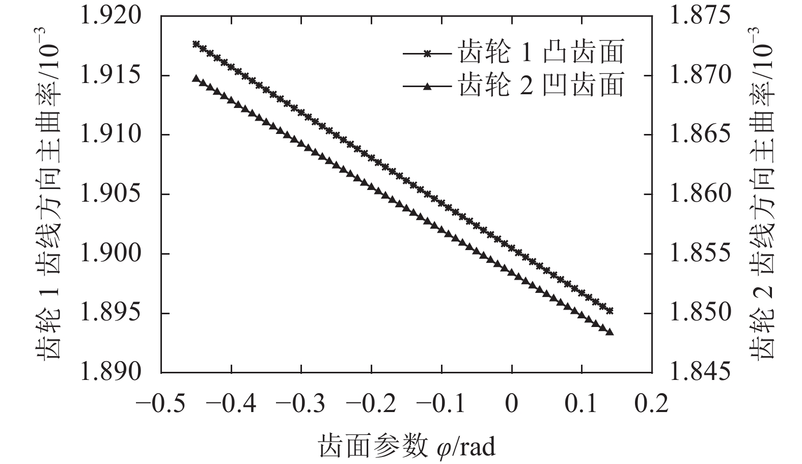 |
| 图4 齿轮齿线方向主曲率 Fig. 4 Principal curvature of VH-CATT gears in the tooth line direction |
从图4可看出齿轮副的凹、凸齿面在齿线方向的主曲率随转角参数
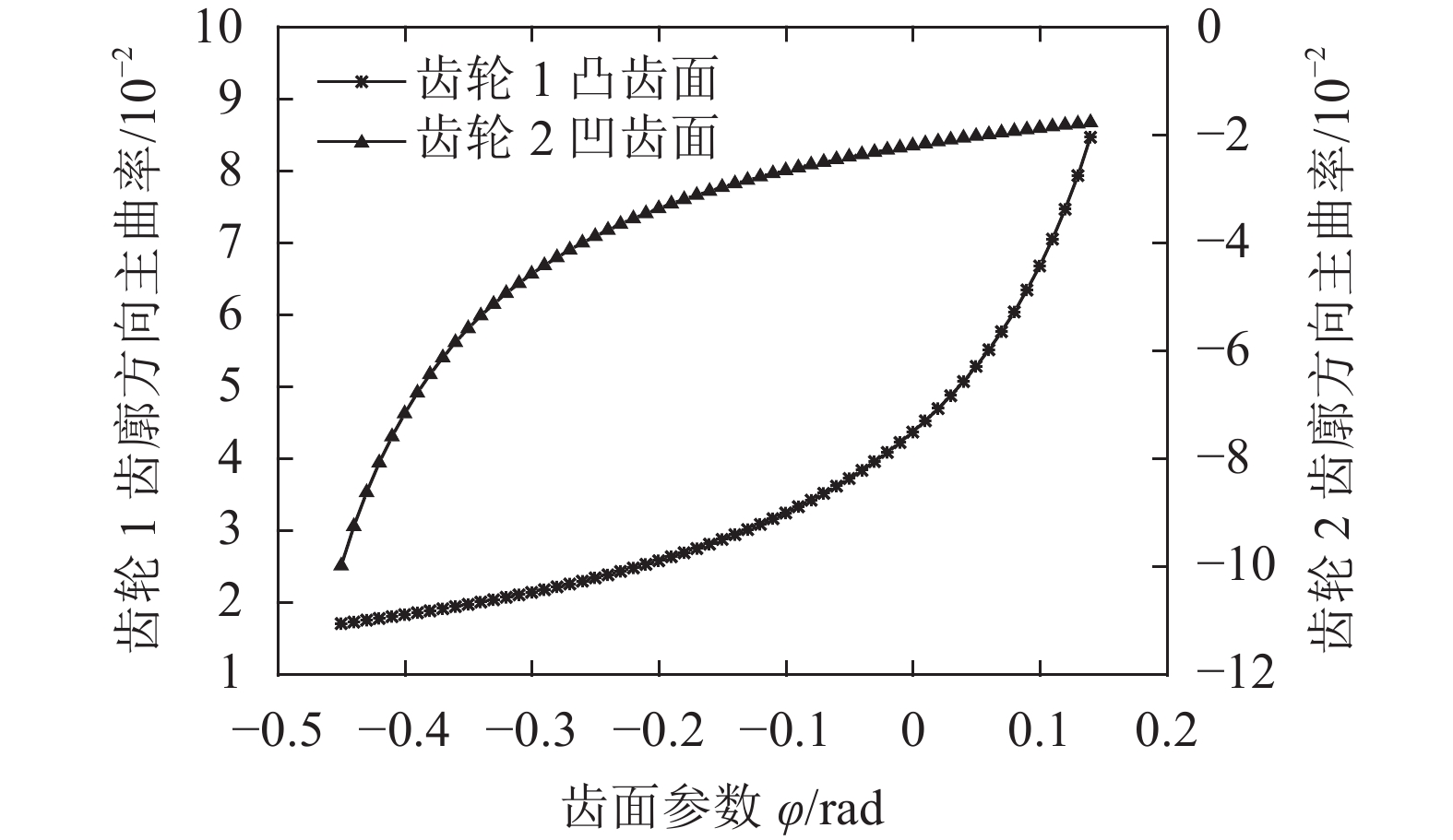 |
| 图5 齿轮副齿廓方向主曲率 Fig. 5 Principal curvature of VH-CATT gears in the tooth profile direction |
从图5看出,齿轮从齿顶到齿根啮合过程中,主动轮1凸齿面齿廓方向主曲率和从动轮2凹齿面齿廓方向主曲率都逐渐增大,在轮齿根位置处,齿轮法曲率达到最大值。主动轮1凸齿面齿廓方向主曲率变化幅度在齿根附近最大,从动轮2凹齿面齿廓方向主曲率增加幅度与主动轮1凸齿面恰好相反,这是由于齿轮凸齿面的成型位置靠近齿根,齿轮凹齿面的成型位置靠近齿顶。并且主曲率的变化趋势与齿形的凹凸性是一致的。
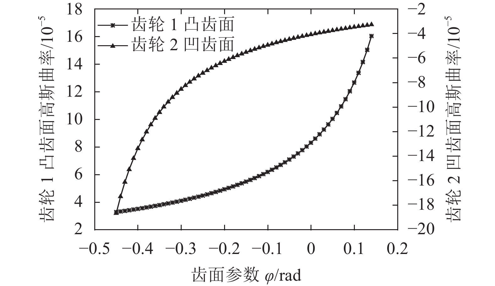 |
| 图6 齿轮副高斯曲率 Fig. 6 Gaussian curvature of VH-CATT gears |
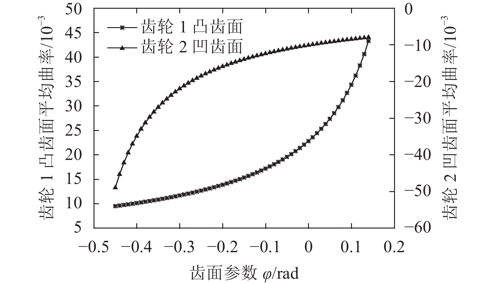 |
| 图7 齿轮副平均曲率 Fig. 7 Mean curvature of VH-CATT gears |
从图6–7可看出,齿轮副的高斯曲率和平均曲率直观地反映了齿轮副齿面的凹凸变化情况,这与高斯曲率和平均曲率所能反映的内蕴几何是一致的;齿轮副的高斯曲率和平均曲率都很小,尤其高斯曲率的绝对值在10–5数量级上,基本接近于0,并且在啮合过程中高斯曲率的变化幅度很小,没有发生突变,这就证明了该齿轮副的光滑程度很高,齿面连续。
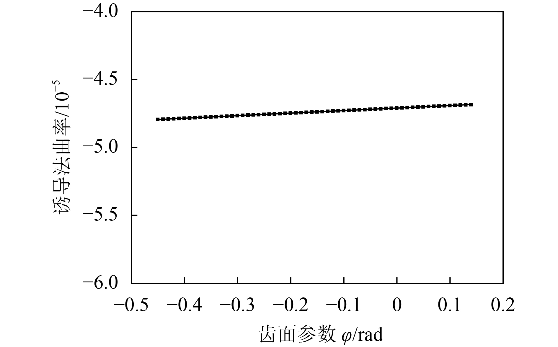 |
| 图8 齿线方向诱导法曲率 Fig. 8 Induced normal curvature of VH-CATT gear in the tooth line direction |
 |
| 图9 齿廓方向诱导法曲率 Fig. 9 Induced normal curvature of VH-CATT gear in the tooth profile direction |
由图8、9可知:在齿线方向齿面诱导法曲率的主值很小,基本接近于0,在齿廓方向的主值为负值,这与文献[26]中规定的若啮合齿面接触点处的公法线矢量方向由齿面的实体指向空域时其诱导法曲率必须为负值是一致的,从而也证明了该齿轮副在啮合过程中没有干涉现象发生。在啮合过程中齿轮副的诱导法曲率在2个主方向上的变化幅度都很小,这也说明了该齿轮的传动性能很好,并且在整个啮合过程中齿轮副处于理想啮合位置;尤其在齿廓方向诱导法曲率绝对值在节圆位置达到最小,恰好也验证了齿轮在啮合过程中节圆附近齿轮传动性能达到最好。啮合过程中,齿轮副齿面在啮合点处曲率连续,达到连接质量,这与该齿轮副传动平稳的结论是一致的。并且很小的诱导法曲率可使该齿轮的接触强度和轮齿抗弯强度较高,这与文献[3–4,21,28]中所论证的变双曲圆弧齿线圆柱齿轮具有较高的弯曲强度和接触强度是一致的。
4 结 论根据大刀盘加工齿轮成型原理,建立了加工变双曲圆弧齿线圆柱齿轮的空间坐标系,通过坐标变换和啮合原理推导了变双曲圆弧齿线圆柱齿轮的齿面方程。
基于齿轮的齿面方程,利用微分几何和啮合原理推导了变双曲圆弧齿线圆柱齿轮的主曲率、高斯曲率、平均曲率和诱导法曲率的数学表达式。
通过数值计算得到了变双曲圆弧齿线圆柱齿轮副算例的齿面数据点和该齿轮的主曲率、高斯曲率、平均曲率和诱导法曲率的变化规律。所得到的数据为计算齿轮综合曲率半径、接触椭圆、接触强度和抗弯强度提供基础,为该齿轮的工业化应用提供设计参考。
| [1] |
Di Yutao.The transmission theroy of cylindrical gears with curvilinear tooth trace[D].Harbin:Harbin Institute of Technology,2006. [狄玉涛.弧齿线圆柱齿轮传动理论的研究[D].哈尔滨:哈尔滨工业大学,2006.]
|
| [2] |
Ma Zhenqun, Wang Xiaochun. Research on a highly durable and heavy duty gearing[J]. Journal of Xi’an Jiaotong University, 2002, 3(36): 282-286. [马振群, 王小椿. 一种高性能重载齿轮的研究[J]. 西安交通大学学报, 2002, 3(36): 282-286.] |
| [3] |
Wang Shaojiang, Hou Li, Dong Lu. Modeling and strength analysis of cylindrical gears with curvilinear shape teeth for manufacture[J]. Journal of Sichuan University (Engineering Science Edition), 2012, 44(3): 210-215. [王少江, 侯力, 董璐. 面向制造的弧齿圆柱齿轮建模及强度分析[J]. 四川大学学报(工程科学版), 2012, 44(3): 210-215.] |
| [4] |
Yan Lili, Hou Li, You Yunxia. Study on forming principle and the maximum contact stress of circular-arc-tooth-trace(CATT) cylinder gear[J]. Journal of Mechanical Transmission, 2014, 38(8): 26-29. [严丽丽, 侯力, 游云霞. 圆弧齿线圆柱齿轮成型原理及最大接触应力研究[J]. 机械传动, 2014, 38(8): 26-29.] |
| [5] |
Chen Zhongmin, Hou Li, Duan Yang. Analysis of nonlinear vibration on a cylindrical gear with variational hyperbola and circular arc tooth trace[J]. Advanced Engineering Sciences, 2017, 49(2): 209-216. [陈忠敏, 侯力, 段阳. 变双曲圆弧齿线圆柱齿轮非线性振动特性分析[J]. 工程科学与技术, 2017, 49(2): 209-216.] |
| [6] |
Hasegawa Yoshimiro, Tada Hiroyuki. Gear cutting machine for circular arc gear[J]. Accretech Machinery, 1952, 18(8): 253-257. [长谷川吉三郎, TadaHiroyuki. 关于圆弧齿线齿轮的切齿机床[J]. 精密机械, 1952, 18(8): 253-257.] |
| [7] |
Koga T.Method for cutting paired gears having arcuate tooth trace:US3915060[P].1975–05–01.
|
| [8] |
Zhu Hailin, Zou Min. The study of the meshing theory of cylindrical gears[J]. Machinery, 1996, 23(5): 7-10. [祝海林, 邹旻. 圆弧齿线圆柱齿轮啮合理论的研究[J]. 机械, 1996, 23(5): 7-10.] |
| [9] |
Zheng Jiang, Cheng Zhigang, Miao Hongbin. Cutting studies on circular ARC tooth trace gear with double arc flank profile[J]. Mechanical Management and Development, 2003(3): 4-5. [郑江, 程志刚, 苗鸿宾. 圆弧齿线双圆弧齿轮的切齿试验研究[J]. 机械管理开发, 2003(3): 4-5.] |
| [10] |
Zou Min. Calculation and selection of the parameters of gear having arcuate tooth traces[J]. Machine Design and Research, 2000(2): 36-38. [邹旻. 圆弧齿线圆柱齿轮的参数计算及选择[J]. 机械设计与研究, 2000(2): 36-38.] |
| [11] |
Dai Yutang, Ariga Yukinori, Jiang Desheng. Hobbing mechanism of cylindrical gear with arcuate tooth traces and experimental investigation[J]. China Mechanical Engineering, 2006, 17(7): 706-709. [戴玉堂, 有贺幸则, 姜德生. 圆弧齿线圆柱齿轮的数控滚切机理与试验研究[J]. 中国机械工程, 2006, 17(7): 706-709.] |
| [12] |
Tseng R T, Tsay C B. Contact characteristics of cylindrical gears with curvilinear shaped teeth[J]. Mechanism and Machine Theory, 2004, 39: 905-919. DOI:10.1016/j.mechmachtheory.2004.04.006 |
| [13] |
Tseng R T, Tsay C B. Mathematical model and surface deviation of cylindrical gears with curvilinear shaped teeth cut by a hob cutter[J]. ASME Journal of Mechanical Design, 2005, 45: 982-987. |
| [14] |
Tseng R T, Tsay C B. Mathematical model and undercutting of cylindrical gears with curvilinear shaped teeth[J]. Mechanism and Machine Theory, 2001, 36: 1189-1202. DOI:10.1016/S0094-114X(01)00049-0 |
| [15] |
Di Yutao, Hong Xiaohui, Chen Ming. Generation principle of arcuate tooth trace cylindrical gear[J]. Journal of Harbin Bearing, 2006, 27(3): 58-61. [狄玉涛, 洪晓晖, 陈明. 弧齿线圆柱齿轮齿面形成原理[J]. 哈尔滨轴承, 2006, 27(3): 58-61.] |
| [16] |
Di Yutao, Chen Ming. The generation principle and mesh characteristic of arcuate tooth trace cylindrical gear[J]. Mechanical Engineer, 2006(9): 50-52. [狄玉涛, 陈明. 弧齿线圆柱齿轮齿面形成原理及啮合性能分析[J]. 机械工程师, 2006(9): 50-52.] |
| [17] |
Song Aiping, Yi Hong, Tang Wencheng. Involute arc cylindrical gear and its mesh characteristics[J]. China Mechanical Engineering, 2006, 17(18): 1888-1892. [宋爱平, 易红, 唐文成. 渐开线弧齿圆柱齿轮及其啮合特性[J]. 中国机械工程, 2006, 17(18): 1888-1892. DOI:10.3321/j.issn:1004-132X.2006.18.005] |
| [18] |
Song Aiping, Wu Weiwei, Gao Shang. The ideal geometry parameters of arch cylindrical gear and its process method[J]. Journal of Shanghai Jiaotong University, 2010, 44(12): 1735-1740. [宋爱平, 吴伟伟, 高尚. 弧齿圆柱齿轮理想几何参数及其加工方法[J]. 上海交通大学学报, 2010, 44(12): 1735-1740.] |
| [19] |
Xiao Huajun, Hou Li, Dong Lu, et al. Mathematical modeling of rotary cutter arc tooth line of cylindrical gear shaped by origin face of rotary cutter[J]. Journal of Sichuan University (Engineering Science Edition), 2013, 45(3): 197-199. [肖华军, 侯力, 董璐. 旋转刀盘母面成形的弧齿圆柱齿轮数学建模[J]. 四川大学学报(工程科学版), 2013, 45(3): 197-199.] |
| [20] |
Jiang Ping, Hou Li, Ren Wenjuan. Molding principle and meshing analysis of curvilinear gear[J]. Machinery Design & Manufacture, 2012, 54(7): 197-199. [姜平, 侯力, 任文娟. 曲线齿轮的成型原理及啮合特性分析[J]. 机械设计与制造, 2012, 54(7): 197-199.] |
| [21] |
Rui Tang L H B Z. Modelling and strength analysis for manufacture oriented cylindrical gear with arcuate tooth trace[J]. Australian Journal of Mechanical Engineering, 2016, 14(2): 88-94. DOI:10.1080/14484846.2015.1093217 |
| [22] |
Zhijun S, Li H, Jinge W. Contact strength analysis of circular-arc-tooth-trace cylindrical gear[J]. Journal of the Brazilian Society of Mechanical Science and Engineer, 2016(38): 999-1005. |
| [23] |
Zhao Fei, Hou Li, Duan Yang, et al. Research on the forming theory analysis and digital model of circular arc gear shaped by rotary cutter[J]. Journal of Sichuan University(Engineering Science Edition), 2016, 48(6): 119-125. [赵斐, 侯力, 段阳. 旋转刀盘圆弧齿轮成形理论及数字化建模研究[J]. 四川大学学报(工程科学版), 2016, 48(6): 119-125.] |
| [24] |
吴序堂.齿轮啮合原理[M].北京:机械工业出版社,1982.
|
| [25] |
李特文.齿轮几何学与应用理论[M].上海:上海科学技术出版社,2008.
|
| [26] |
Zhang Xiaorong, Lu Bo. The calculation of induced normal curvature of the helical cylindrical gear with parallel axes[J]. Modern Manufacturing Engineering, 2008(4): 107-110. [张晓蓉, 陆波. 平行轴斜齿轮诱导法曲率计算[J]. 现代制造工程, 2008(4): 107-110.] |
| [27] |
Cleve Moler.Experiments with MATLAB[M].Beijing,Beijing Aerospace University Press,2013.
|
| [28] |
Jia Fenglan, Hou Li, Wei Yongqiao. Modeling and bending strength analysis of cylindrical gears with arcuate tooth trace[J]. Australian Journal of Mechanical Engineering, 2015, 13(2): 77-86. DOI:10.7158/M13-068.2015.13.2 |
 2017, Vol. 49


