谐振腔天线因结构简洁,易于实现高增益,平面结构等优点得到了广泛的研究与应用[1–3]。根据射线光学法[1],谐振腔天线通过其部分反射层与金属地间的多次反射,在口径面上形成同相口径场,从而获得高增益。但是,射线光学法是一种近似方法[4–5]。Afzal等[6–9]指出,谐振腔天线的口径场相位为不均匀分布,其造成谐振腔天线的增益较低。
为了获得高增益谐振腔天线,具有高透射系数幅值,且可以改变入射电磁波相位的相移层被设计并用于修正谐振腔天线的不均匀口径场相位分布[6–9]。Afzal等[6]设计了一款连续介质相移层,并加载于一个直径为6个波长的圆柱形谐振腔天线上,该研究结果表明谐振腔天线加载相移结构后,获得了一个更加均匀的口径场相位分布,天线增益由原有的13.4 dB增加到了20.8 dB。此外,Afzal等[7]还设计了一款阶梯状介质相移层,也成功提高了谐振腔天线的增益。但是,两种相移层[6–7]均采用介质设计,存在着体积大,重量重,加工制作困难等缺点。
近些年来,拥有优良性能的电磁超材料被提出,并得到广泛研究[10]。通过改变电磁超材料的形状和尺寸,可以得到不同的透射系数,从而实现超材料相移层[11]。Afzal等[8]设计了一款超材料相移层,其相移层单元由印刷在双层印刷电路板(printed circuit board,PCB)上的3层金属块组成;通过调节金属块的边长,实现不同的相移角度。但是,该超材料相移层[8]仅仅依靠全波仿真和参数扫描进行设计,需要大量的计算时间,不利于工程实现。Zhou等[9]提出了基于全波仿真和等效电路法的混合设计方法,实现了超材料相移层的快速设计。但是,为了避免金属层之间的强互耦,其金属层间的间距较大,该相移层的高度较高。
惠更斯超表面[12–13]是一种新型的超材料,可以同时与入射电磁波的电场与磁场进行谐振响应,拥有更加优良的电磁性能。作者采用惠更斯超表面设计了一款相移层,并将其应用于谐振腔天线上,提高天线口径场相位分布的均匀性,实现高增益。该超表面相移层由独立与磁场和电场谐振的两组开口谐振环组成,通过分别设计电场谐振和磁场谐振强度,实现相移层的快速设计。该相移层采用PCB板制备,具有重量轻,厚度薄,加工制备简单等优势。作者设计、加工、实测了一款工作频率5.8 GHz的加载惠更斯超表面相移层的谐振腔天线,验证了设计方法的有效性。
1 惠更斯超表面相移层惠更斯超表面是一种同时拥有电谐振与磁谐振的新型超材料[12]。该超表面的电磁性能可以通过表面电导纳
如图1所示,当惠更斯超表面受到平行于
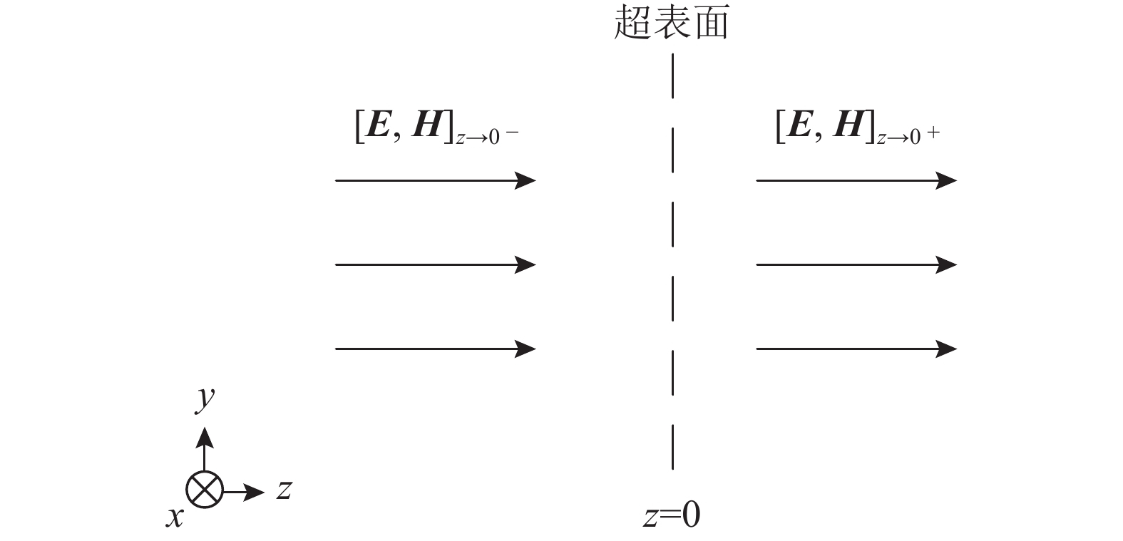 |
| 图1 在电磁波入射下的超表面示意图 Fig. 1 Schematic of the metasurface under the incident electromagnetic wave |
| $\begin{aligned}[b]&\left[{{z}} \times ({\left. {{H}} \right|_{{\textit{z}} \to {0^ + }}} - {\left. {{H}} \right|_{{\textit{z}} \to {0^ - }}})\right] = \\&{Y_{{\rm{se}}}} \cdot \,\left({\left. {{{{E}}_{{\rm{tan}}}}} \right|_{{\textit{z}} \to {0^ + }}} + {\left. {{{{E}}_{{\rm{tan}}}}} \right|_{{\textit{z}} \to {0^ - }}}\right)/2\end{aligned}$ | (1) |
| $\begin{aligned}[b]&[ - {{z}} \times ({\left. {{E}} \right|_{{\textit{z}} \to {0^ + }}} - {\left. {{E}} \right|_{{\textit{z}} \to {0^ - }}})] = \\&{{\textit{Z}}_{{\rm{sm}}}} \cdot ({\left. {{{{H}}_{{\rm{tan}}}}} \right|_{{\textit{z}} \to {0^ + }}} + {\left. {{{{H}}_{{\rm{tan}}}}} \right|_{{\textit{z}} \to {0^ - }}})/2\end{aligned}$ | (2) |
式(1)~(2)中,
| ${\left. {{E}} \right|_{{\textit{z}} \to {0^ + }}} = {\left. {{E}} \right|_{{\textit{z}} \to {0^ - }}} \cdot {{\rm{e}}^{{\rm{j}}\theta }}$ | (3) |
| ${\left. {{H}} \right|_{{\textit{z}} \to {0^ + }}} = {\left. {{H}} \right|_{{\textit{z}} \to {0^ - }}} \cdot {{\rm{e}}^{{\rm{j}}\theta }}$ | (4) |
式中,
| ${Y_{{\rm{se}}}}\eta = {{\textit{Z}}_{{\rm{sm}}}}/\eta = - {\rm{j}}\tan (\theta /2)$ | (5) |
由方程(5)可以看出,通过改变超表面的
图2为作者采用的惠更斯相移层单元的结构图[13],其由印制于双层PCB板上的两组开口谐振环[14]组成,两组分别位于
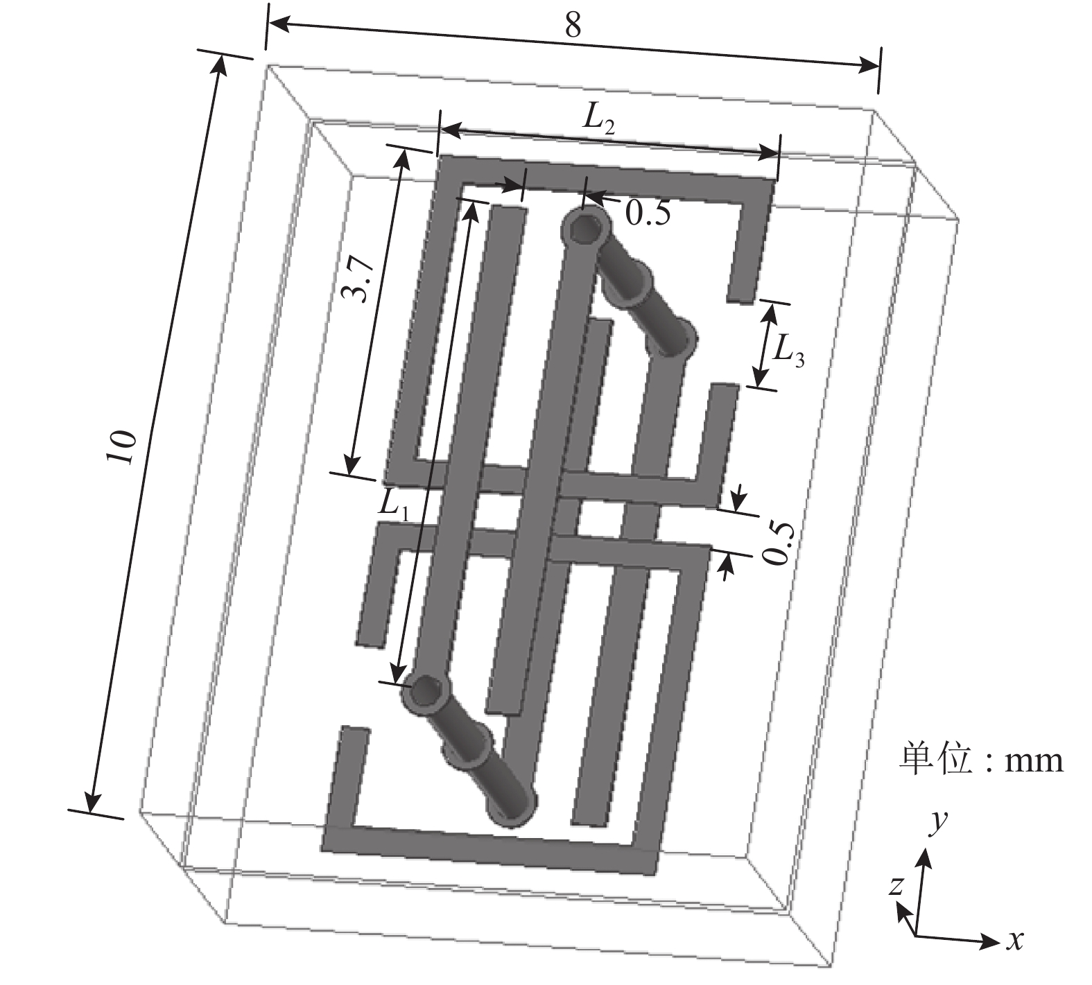 |
| 图2 惠更斯超表面的单元模型图 Fig. 2 Configuration of the unit cell of the Huygens’ metasurface |
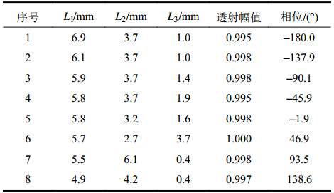
基于上述方法,作者设计了一系列工作于5.8 GHz的惠更斯超表面相移层单元。表1列出了其中一部分相移层单元的尺寸参数与其所具有的透射系数幅值和相位。从表1可以看出,惠更斯超表面相移层可以实现360°相移,并保持透射系数幅值大于0.99。
| 表1 部分相移层单元的尺寸参数和透射系数幅值相位 Tab. 1 Dimensions and transmission magnitudes and phases of some PSS unit cells |
 |
2 加载相移层的谐振腔天线设计
加载惠更斯超表面相移层的谐振腔天线的结构如图3所示。其中,谐振腔天线为圆柱形,直径
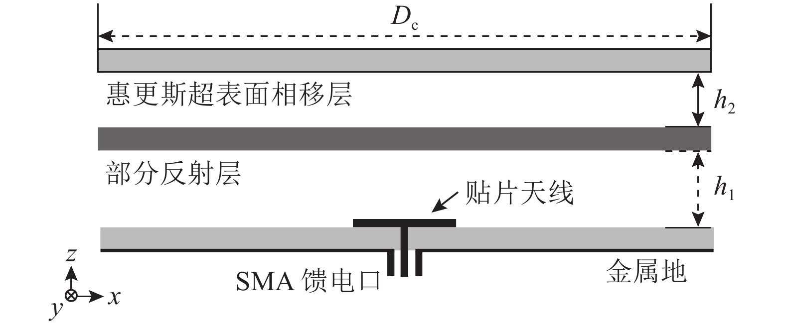 |
| 图3 加载惠更斯超表面相移层的谐振腔天线的结构图 Fig. 3 Configuration of the resonant cavity antenna with the Huygens’ metasurface as the phase shift surface |
惠更斯超表面相移层位于谐振腔天线口径正上方,相移层与部分反射层间的距离
对加载了相移层的谐振腔天线进行CST全波仿真,得到了其口径场相位分布。图4为加载和未加载相移层情况下,谐振腔天线口径场沿
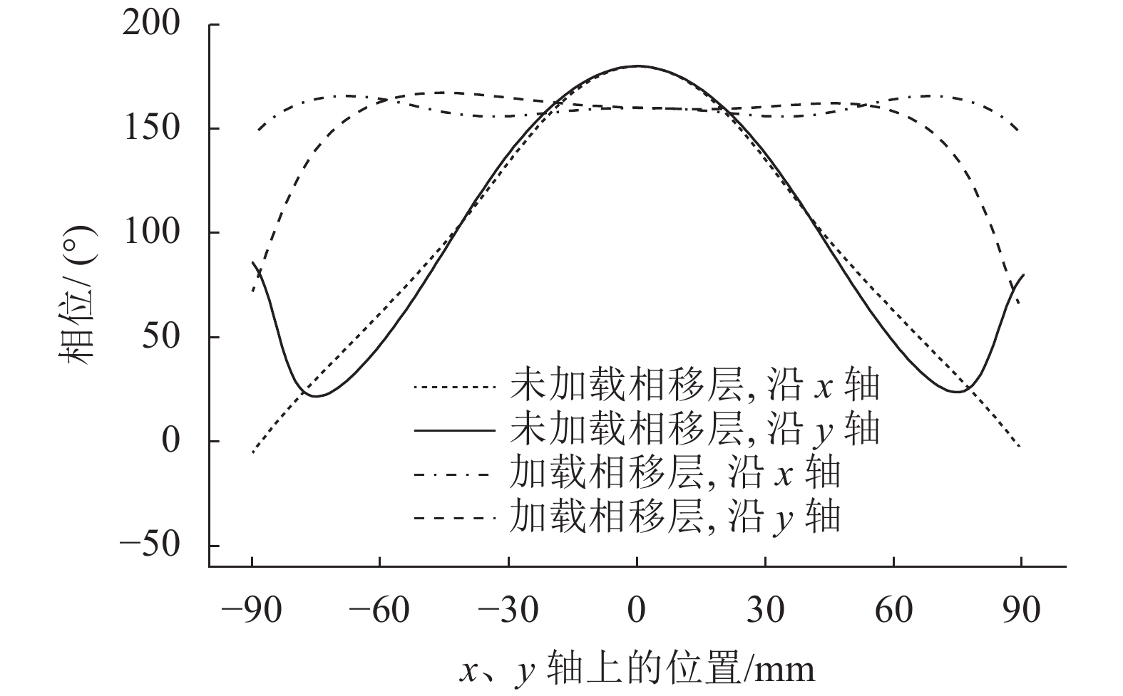 |
|
图4 加载和未加载相移层的谐振腔天线口径场沿
|
图5给出了加载和未加载相移层的谐振腔天线的仿真方向图。从图5可以看出,加载相移层后,谐振腔天线增益有明显的升高,由原来的14.90 dB升高到18.31 dB,其对应的口径效率由原来的25.9%提高到了56.7%。
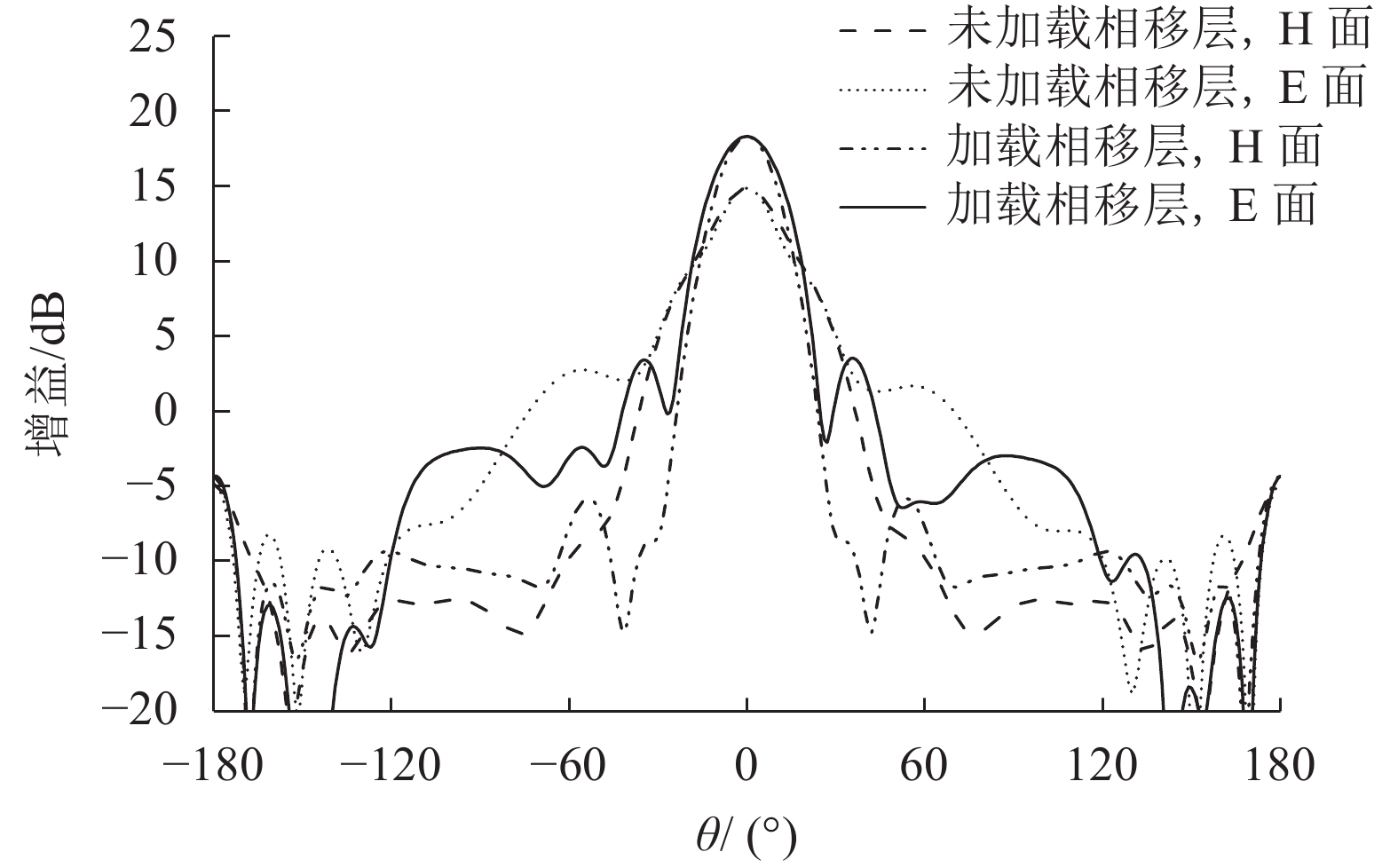 |
| 图5 加载和未加载相移层的谐振腔天线仿真方向图 Fig. 5 Simulated radiation patterns of the RCA with or without the PSS |
3 天线加工实测
对设计的加载惠更斯超表面相移层的谐振腔天线进行了加工,其实物图如图6所示。
 |
| 图6 加载相移层的谐振腔天线的实物图 Fig. 6 Prototype of the RCA with the PSS |
对加工的天线进行测试,并与仿真结果进行对比。天线的输入反射系数由安捷伦E8362B测得,结果如图7所示。从图7可以看到,测试结果和仿真结果吻合良好。加载相移层的谐振腔天线的实测|
 |
|
图7 天线的仿真和实测输入反射系数|
|
天线的辐射特性在微波暗室中测得。图8绘制了加载相移层的谐振腔天线在5.8 GHz时的仿真和实测辐射方向图。
从图8可以看出,实测结果与仿真值吻合良好,天线具有高增益。同时,天线的实测主旁瓣比大于15 dB,半功率波束角内交叉极化比大于20 dB。
 |
| 图8 天线5.8 GHz时的仿真和实测辐射方向图 Fig. 8 Simulated and measured radiation patterns of the antenna at 5.8 GHz |
4 结 论
为了获得高增益谐振腔天线,作者设计了一款惠更斯超表面相移层,将其加载于谐振腔天线表面,用于修正天线的口径场相位分布。该惠更斯超表面的电场谐振与磁场谐振相互独立,可以分别调节,从而实现了相移层的快速设计。为验证方法的正确性,采用该结构设计了一款工作频率5.8 GHz的相移层,并将其加载于直径180 mm的谐振腔天线上。CST全波仿真和加工实测结果表明,通过加载惠更斯超表面相移层,谐振腔天线的口径场相位分布变得更加均匀,增益也获得了显著提高。虽然本研究仅将惠更斯超表面相移层应用于谐振腔天线,但其同样可以应用于具有不均匀口径场相位分布的其他天线类型。下一步研究中,作者将把所设计的相移层应用于微带阵列天线和波导缝隙天线,以提高天线的辐射性能。
| [1] |
Trentini G V. Partially reflecting sheet arrays[J]. IRE Transactions on Antennas and Propagation, 1956, 4(4): 666-671. DOI:10.1109/TAP.1956.1144455 |
| [2] |
Feresidis A P,Vardaxoglou J C. High gain planar antenna using optimised partially reflective surfaces[J]. IEE Proceedings-Microwaves,Antennas and Propagation, 2001, 148(6): 345-350. DOI:10.1049/ip.map:20010828 |
| [3] |
Jackson D,Alexopoulos N. Gain enhancement methods for printed circuit antennas[J]. IEEE Transactions on antennas and Propagation, 1985, 33(9): 976-987. DOI:10.1109/TAP.1985.1143709 |
| [4] |
Foroozesh A,Shafai L. Investigation into the effects of the reflection phase characteristics of highly-reflective superstrates on resonant cavity antennas[J]. IEEE Transactions on Antennas and Propagation, 2010, 58(10): 3392-3396. DOI:10.1109/TAP.2010.2055810 |
| [5] |
Zhou Lin,Chen Xing,Cui Yuguo,et al. Comparative effects of capacitive and inductive superstrates on the RCA’s gain[J]. IET Microwaves,Antennas & Propagation, 2018, 12(11): 1834-1838. DOI:10.1049/iet-map.2017.1062 |
| [6] |
Afzal M U,Esselle K P. Quasi-analytical synthesis of continuous phase correcting structures to increase the directivity of circularly polarized Fabry-Perot resonator antennas[J]. Journal of Applied Physics, 2015, 117(21): 214902. DOI:10.1063/1.4921971 |
| [7] |
Afzal M U,Esselle K P,Zeb B A. Dielectric phase-correcting structures for electromagnetic band gap resonator antennas[J]. IEEE Transactions on Antennas and Propagation, 2015, 63(8): 3390-3399. DOI:10.1109/TAP.2015.2438332 |
| [8] |
Afzal M U,Esselle K P. A low-profile printed planar phase correcting surface to improve directive radiation characteristics of electromagnetic band gap resonator antennas[J]. IEEE Transactions on Antennas and Propagation, 2016, 64(1): 276-280. DOI:10.1109/TAP.2015.2493159 |
| [9] |
Zhou Lin,Chen Xing,Duan Xin,et al. FPA using a three-layer PSS for gain enhancement[J]. IET Microwaves,Antennas & Propagation, 2017, 12(3): 400-405. DOI:10.1049/iet-map.2017.0522 |
| [10] |
Sihvola A. Metamaterials in electromagnetics[J]. Metamaterials, 2007, 1(1): 2-11. DOI:10.1016/j.metmat.2007.02.003 |
| [11] |
Gagnon N.Phase shifting surface (PSS) and phase and amplitude shifting surface (PASS) for microwave applications[M].Ottawa:University of Ottawa,2011.
|
| [12] |
Epstein A,Eleftheriades G V. Huygens’ metasurfaces via the equivalence principle:Design and applications[J]. Journal of the Optical Society of America B, 2016, 33(2): A31-A50. DOI:10.1364/JOSAB.33.000A31 |
| [13] |
Jia S L,Wan X,Fu X J,et al. Low-reflection beam refractions by ultrathin Huygens metasurface[J]. AIP Advances, 2015, 5(6): 067102. DOI:10.1063/1.4922062 |
| [14] |
Katsarakis N,Koschny T,Kafesaki M,et al. Electric coupling to the magnetic resonance of split ring resonators[J]. Applied Physics Letters, 2004, 84(15): 2943-2945. DOI:10.1063/1.1695439 |
| [15] |
Hirtenfelder F.Effective antenna simulations using CST MICROWAVE STUDIO®[C]//Proceedings of 2007 2nd International ITG Conference on Antennas.Munic:IEEE,2007:239-239.
|
 2018, Vol. 50


